A solar panel wiring diagram is a visual guide illustrating the electrical connections and components of a solar panel system․ It serves as a blueprint for installation, ensuring safety and efficiency by detailing how panels, inverters, batteries, and other components are interconnected․ These diagrams are essential for understanding the flow of electricity and troubleshooting issues, providing a clear roadmap for both novice installers and experienced technicians․
What is a Solar Panel Wiring Diagram?
A solar panel wiring diagram is a detailed visual representation of a solar panel system’s electrical connections and components․ It provides a clear and organized illustration of how solar panels, inverters, batteries, charge controllers, and other system elements are interconnected․ The diagram uses standardized symbols and labels to depict each component and the flow of electricity, ensuring that installers and technicians can understand and implement the connections accurately․ By outlining the electrical pathways and relationships between parts, it serves as an essential guide for installation, troubleshooting, and maintenance․ This ensures safety, efficiency, and compliance with electrical standards, making it a crucial tool for both professionals and DIY enthusiasts working with solar power systems․
Importance of Solar Panel Wiring Diagrams
Solar panel wiring diagrams are crucial for ensuring the safe and efficient installation of solar panel systems․ They provide a clear visual representation of electrical connections, helping to prevent errors that could lead to short circuits or fires․ Proper wiring ensures maximum energy production by optimizing the flow of electricity between panels, inverters, and batteries․ These diagrams also simplify maintenance and troubleshooting, allowing technicians to quickly identify and resolve issues․ Compliance with electrical standards is another key benefit, as diagrams help verify that installations meet safety and regulatory requirements․ Ultimately, wiring diagrams are essential for the reliable and efficient operation of solar power systems, ensuring both performance and safety․
Why Use a Wiring Diagram for Solar Panels?
A wiring diagram for solar panels is essential for ensuring a safe, efficient, and compliant installation․ It provides a clear roadmap for connecting components like panels, inverters, and batteries, minimizing the risk of electrical hazards․ By following a diagram, installers can avoid common mistakes that might lead to system malfunctions or safety issues․ Additionally, it simplifies the troubleshooting process, allowing technicians to quickly identify and resolve problems․ A wiring diagram also ensures that the system operates at maximum efficiency, optimizing energy production․ For both novice and experienced installers, a wiring diagram is an invaluable tool that guarantees a reliable and properly functioning solar panel system, adhering to electrical standards and best practices․
Understanding the Components of a Solar Panel System
A solar panel system consists of panels, inverters, batteries, charge controllers, and mounting structures․ These components work together to generate, store, and distribute renewable energy efficiently and safely․
Solar Panels: The Core Component
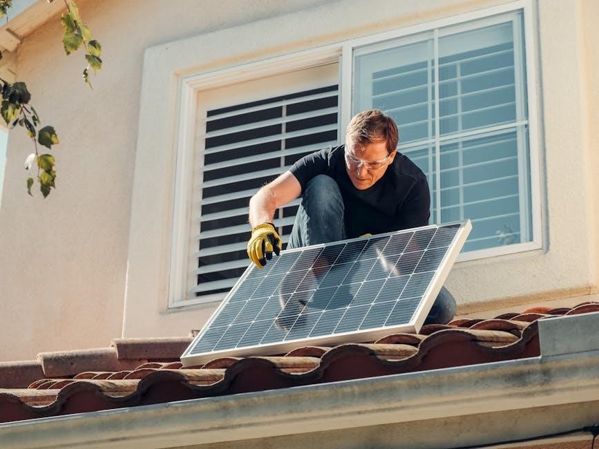
Solar panels are the heart of any solar panel system, converting sunlight into electricity through photovoltaic cells․ They are designed to capture solar energy efficiently and are typically made from silicon․ Panels are grouped into arrays to increase energy output․ Proper installation and wiring, as shown in a solar panel wiring diagram, ensure optimal performance․ The panels are durable, with lifespans often exceeding 25 years, and require minimal maintenance․ Their efficiency depends on factors like material quality, sunlight exposure, and temperature․ While panels are reliable, their output can vary due to weather conditions․ As the primary energy source, solar panels are essential for generating power, making them the foundation of any solar energy system․
Inverters: Converting Solar Energy to Usable Power
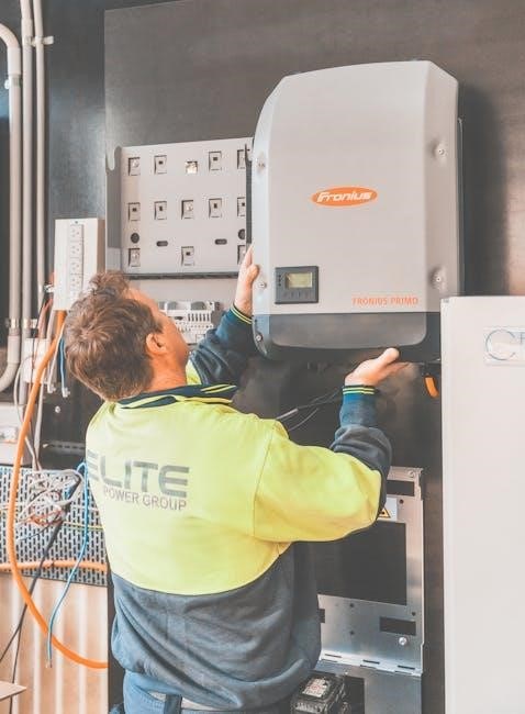
Inverters are critical components in solar panel systems, responsible for converting direct current (DC) energy generated by solar panels into alternating current (AC) electricity, which powers household appliances․ They ensure compatibility between the solar array’s output and the electrical grid or local load․ Modern inverters often include advanced features like maximum power point tracking (MPPT) to optimize energy production․ Solar panel wiring diagrams detail how inverters are connected to panels, batteries, and the grid․ Proper installation and wiring are essential for safety and efficiency․ Inverters also provide monitoring capabilities, allowing users to track system performance․ Their reliability and efficiency are vital for ensuring consistent energy supply, making them indispensable in solar energy systems․
Batteries: Storing Excess Energy
Batteries play a crucial role in solar panel systems by storing excess energy generated during sunny periods for use during cloudy days or at night․ They ensure a consistent power supply, even when sunlight is unavailable․ Deep-cycle batteries, such as lead-acid or lithium-ion, are commonly used for their ability to store and release large amounts of energy․ Solar panel wiring diagrams detail how batteries are integrated into the system, connecting them to solar panels, inverters, and charge controllers․ Proper wiring ensures safe and efficient energy storage, preventing overcharging or deep discharging․ Batteries are essential for off-grid systems but also enhance grid-tied setups by providing backup power during outages․ Their capacity and type are selected based on energy needs and system design, as outlined in the wiring diagram․
Charge Controllers: Regulating Energy Flow
Charge controllers are essential components in solar panel systems, regulating the energy flow from solar panels to batteries․ Their primary function is to prevent overcharging or excessive discharge, ensuring the battery operates within safe voltage and current levels․ By monitoring the battery’s state of charge, charge controllers optimize energy storage and extend battery lifespan․ They also protect the system from reverse current flow at night, which can drain the battery․ Solar panel wiring diagrams illustrate how charge controllers are connected in the circuit, typically between the panels and the battery bank․ Proper installation and configuration of charge controllers are critical for maintaining system efficiency, safety, and reliability, especially in off-grid setups where energy management is paramount․
Mounting Structures: Securing the Solar Panels
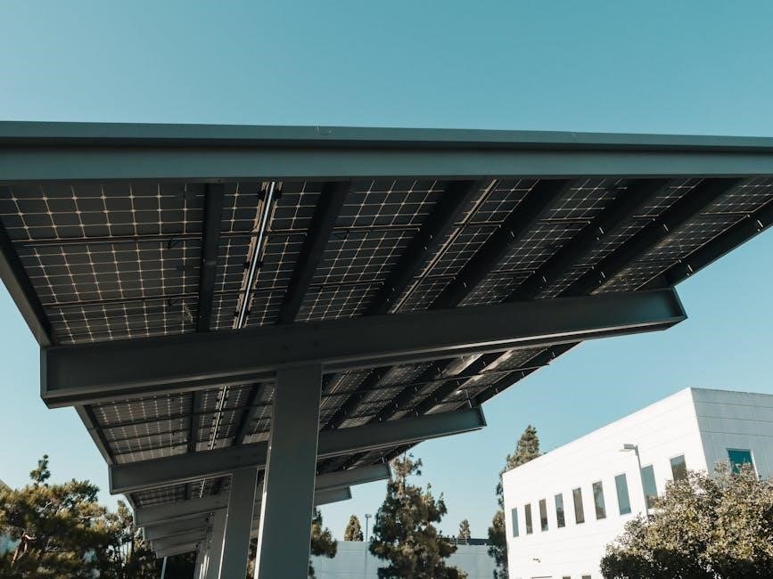
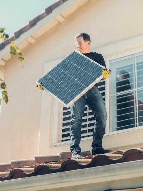
Mounting structures are crucial for securing solar panels in a solar panel system․ These structures, such as racks, brackets, and trackers, ensure panels are properly aligned and elevated for maximum sunlight exposure․ They are designed to withstand environmental stresses like wind, rain, and extreme temperatures․ Solar panel wiring diagrams often include details about how mounting structures integrate with the system, emphasizing their role in maintaining stability and efficiency․ Proper installation of mounting hardware ensures panels remain secure, reducing the risk of damage or misalignment․ Durable materials and adjustable designs allow for customization to suit different rooftops or ground-mounted setups, optimizing energy production and system longevity․
Types of Solar Panel Wiring Configurations
Solar panel wiring configurations include series, parallel, and combination setups․ Series wiring increases voltage, parallel boosts current, and combination offers flexibility for varying energy needs and system sizes․
Series Wiring: Connecting Panels for Higher Voltage
In a series wiring configuration, solar panels are connected end-to-end, allowing the voltage to add up while the current remains consistent․ This setup is ideal for systems requiring higher voltage levels, such as grid-tied configurations or when charging batteries at a higher voltage․ Each panel’s voltage contributes to the total system voltage, making it suitable for applications with specific voltage requirements․ However, series wiring can be less flexible, as shading or issues with one panel affect the entire chain․ Proper matching of panel specifications is crucial to avoid imbalances and ensure optimal performance․ Series wiring is straightforward but requires careful planning to meet system demands effectively․
Parallel Wiring: Connecting Panels for Higher Current
Parallel wiring connects solar panels by linking their positive terminals together and negative terminals together, increasing the system’s current capacity while maintaining voltage․ This configuration is ideal for setups requiring higher current to meet energy demands․ Unlike series wiring, parallel wiring offers flexibility; if one panel underperforms, others continue to function, ensuring system reliability․ However, mismatched panels may reduce efficiency․ Parallel wiring is scalable, allowing easy addition of more panels․ It’s commonly used in systems with varying conditions, like shaded areas․ Proper wire sizing and safety components, such as circuit breakers, are essential to handle increased current safely․ This setup balances performance, flexibility, and ease of expansion effectively․
Combination of Series and Parallel Wiring
A combination of series and parallel wiring offers flexibility and efficiency in solar panel systems․ This setup involves grouping panels in series to increase voltage, then connecting these groups in parallel to boost current․ This configuration balances voltage and current levels, maximizing energy output․ It’s ideal for larger systems or installations with varying conditions, such as shading․ The combination setup allows for scalability, enabling easy addition of more panels or groups․ Proper planning ensures optimal performance, while redundancy provides reliability if one group underperforms․ This method is widely used in both grid-tie and off-grid systems․ Always follow safety standards and manufacturer guidelines for wiring to ensure efficiency and durability․
Safety Considerations in Solar Panel Wiring
Understanding voltage, current, and power ratings is crucial for safe solar panel wiring․ Protecting against short circuits, overloads, and proper grounding ensures system reliability and user safety․
Understanding Voltage, Current, and Power Ratings

Understanding voltage, current, and power ratings is essential for the safe and efficient design and installation of solar panel systems․ Voltage measures the electrical potential difference, current the flow rate of electrons, and power, as the product of voltage and current, indicates the energy output․ Accurate knowledge of these ratings ensures compatibility between components, preventing overload and optimizing system performance․ Solar panel wiring diagrams provide these specifications to guide proper connections and configurations, minimizing risks of inefficiencies or hazards․ Mismatched ratings can lead to reduced efficiency, increased wear on components, or even safety hazards such as overheating․ Therefore, precise planning and adherence to specified ratings are crucial․ Consulting a professional for complex setups ensures safety and compliance with electrical standards, guaranteeing a reliable and efficient solar energy system․
Protecting Against Short Circuits and Overloads
Protecting against short circuits and overloads is critical to ensure the safety and reliability of a solar panel system․ A short circuit occurs when electrical current flows through an unintended path, causing excessive current and heat․ Overloads happen when the system exceeds its maximum current capacity, leading to overheating and potential damage․ To prevent these issues, circuit breakers and fuses are essential; they interrupt the electrical flow during overloads or short circuits․ Proper wire sizing is also crucial to handle maximum current without overheating․ Grounding the system ensures safe voltage levels and allows protective devices to function effectively․ Surge protectors guard against voltage spikes, while regular inspections of wiring and connections help identify and rectify potential issues․ Adhering to the solar panel wiring diagram ensures all components are appropriately rated and configured, enhancing overall system safety and performance․
Grounding the Solar Panel System for Safety
Grounding the solar panel system is essential for ensuring safety and protecting against electrical hazards․ A properly grounded system provides a safe path for excess electrical current to the earth, preventing dangerous voltage levels in the system․ Grounding also protects against lightning strikes and power surges, safeguarding both people and equipment․ A ground fault circuit interrupter (GFCI) is often used to detect and interrupt ground faults, further enhancing safety․ Proper grounding ensures the system operates within safe voltage levels and allows protective devices to function correctly․ Regular inspections of grounding connections are crucial to maintain the integrity of the solar panel system․ Always follow the solar panel wiring diagram to ensure correct grounding procedures are implemented․

Step-by-Step Guide to Reading a Solar Panel Wiring Diagram
Start by identifying components like panels, inverters, and batteries․ Trace connections to understand energy flow․ Refer to the solar panel wiring diagram PDF for accurate guidance;
Identifying Symbols and Labels
Begin by locating standard symbols for solar panels, inverters, batteries, and connectors in the wiring diagram․ These symbols are universally recognized and simplify understanding․ Labels provide detailed information about each component, such as wattage, voltage, and model numbers․ Pay attention to color-coded lines, which indicate live, neutral, or ground wires․ Cross-reference keys in the PDF explain unfamiliar symbols, ensuring clarity․ Properly identifying these elements is essential for tracing connections and diagnosing issues․ This step forms the foundation for accurately interpreting the entire wiring layout and troubleshooting any potential faults in the system․ Always refer to the legend or key provided in the diagram for precise identification․
Understanding the Flow of Electricity
Electrical flow in a solar panel system begins with energy generation from the panels and moves through the wiring to essential components․ The wiring diagram illustrates this flow, showing how current travels from panels to the charge controller, then to the battery bank, and finally to the inverter․ From there, it powers electrical loads or feeds back into the grid․ Always follow the diagram to trace the path of electricity, ensuring connections are logical and safe; This understanding helps identify potential bottlenecks and ensures efficient energy distribution․ Familiarizing yourself with the flow prevents misconnections and enhances system reliability․ Use the diagram to verify proper routing and operation, ensuring all components function as intended․
Interpreting Wiring Colors and Codes
Understanding wiring colors and codes is crucial for safely and effectively installing solar panel systems․ In most diagrams, wires are color-coded to indicate their purpose: black for positive, red for positive DC, white for negative, and green for ground․ These colors help technicians quickly identify connections and avoid dangerous miswiring․ Additionally, codes on wires may specify voltage, current, or resistance ratings․ For example, labels like “12AWG” indicate wire gauge and suitability for specific currents․ Always refer to the wiring diagram and manufacturer’s guidelines to interpret these codes accurately․ Proper identification ensures compliance with safety standards and optimal system performance․ This step is vital for both installation and troubleshooting processes․
Troubleshooting Common Wiring Issues
Identify open circuits, short circuits, or ground faults using multimeters and fault finders․ Check connections, fuses, and wiring for damage or corrosion; Reference the wiring diagram to locate faults efficiently and ensure repairs align with system design․ Always follow safety guidelines to prevent electrical hazards during troubleshooting․
Identifying Faults in the Wiring Diagram
To identify faults in a solar panel wiring diagram, start by comparing the physical setup with the diagram to ensure all connections match․ Use a multimeter to check for voltage and current discrepancies, which can indicate short circuits or open circuits․ Look for components in the diagram that are highlighted or marked differently, as these may signify common fault areas․ Utilize color codes and labels in the diagram to pinpoint potential issues․ Consider using software tools to simulate the wiring and help locate faults without physical inspection․ A systematic, step-by-step approach is crucial for methodically checking each component and connection․ Familiarity with electrical principles and practice can enhance fault identification accuracy․
Checking for Loose Connections
Checking for loose connections in a solar panel wiring diagram is essential to ensure system efficiency and safety․ Begin by reviewing the wiring diagram to locate all connectors, terminals, and junction points; Visually inspect each connection for signs of wear, oxidation, or damage․ Use a multimeter to test continuity and resistance, which can help detect loose or faulty connections․ Gently tug on wires to identify any that feel disconnected or unstable․ Tighten all loose connections securely, ensuring they meet the manufacturer’s torque specifications; Regularly inspect and maintain connections to prevent energy loss and potential electrical hazards․ Properly secured connections are vital for optimal system performance and longevity․
Verifying Voltage and Current Levels
Verifying voltage and current levels is critical to ensure your solar panel system operates safely and efficiently․ Refer to your wiring diagram to identify test points for voltage and current measurements․ Use a multimeter to measure voltage across panels or components, comparing the readings to the specifications provided in the wiring diagram․ Check current levels at key points, such as the output of the inverter or charge controller․ Ensure all measurements align with the expected values to confirm proper system performance․ If readings are inconsistent, investigate potential issues like faulty connections or component failures․ Accurate verification helps maintain system reliability and prevents electrical hazards․ Regular checks are essential for long-term efficiency and safety․
Best Practices for Solar Panel Wiring
Adhere to your solar panel wiring diagram and safety standards․ Use high-quality, UV-resistant wires and connectors․ Label all wires clearly for easy identification․ Follow local electrical codes․ Test connections before energizing․ Regularly inspect wires for damage․ Ensure proper grounding․ Use fuses or circuit breakers․ Keep wiring organized to prevent tangling․ Consult professionals for complex setups․ Ensure all connections are secure and weatherproof․ Regular maintenance enhances system performance and longevity․ Always follow manufacturer guidelines for components․ Proper wiring ensures safety, efficiency, and durability of your solar panel system․ Stay informed about updates or changes in wiring standards․ Prioritize safety and precision in every connection․ Use appropriate tools for wiring tasks․ Keep records of your wiring configuration for future reference․ Plan for scalability in case of system expansion․ Ensure compliance with local regulations and permits․ Use color-coded wires for consistency and clarity․ Protect wires from extreme temperatures and environmental stress․ Avoid overloading circuits to prevent failures․ Regularly clean and inspect connectors for corrosion․ Replace worn-out components promptly․ Maintain proper documentation for troubleshooting and repairs․ Stay updated with industry best practices․ Always turn off power before performing maintenance․ Use protective gear when handling electrical components․ Ensure all wires are properly insulated and sealed․ Verify polarity when connecting components․ Use locking connectors for secure connections․ Avoid mixing different wire sizes unnecessarily․ Keep wiring accessible for future servicing․ Follow proper torque specifications for connections․ Use compatible materials to prevent corrosion․ Ensure all wiring meets load requirements․ Avoid sharp bends in wires to prevent damage․ Use cable ties or clips to secure wires neatly․ Protect wires from pests and rodents․ Regularly check for signs of wear or degradation․ Ensure all connections are tight and secure․ Use surge protectors to safeguard against voltage spikes․ Keep emergency shutdown procedures accessible․ Ensure all wiring is well-ventilated to prevent overheating․ Use appropriate fasteners for mounting wiring components․ Avoid over-twisting or pinching wires during installation․ Ensure all wiring is compatible with system voltage and current ratings․ Use proper sealing methods for outdoor connections․ Keep spare wiring and connectors on hand․ Document all changes or updates to the wiring system․ Ensure all wiring is free from insulation damage․ Use correct crimping tools for connectors․ Avoid cross-connecting wires from different circuits․ Use voltage drop calculations to size wires correctly․ Ensure all wiring is protected from physical stress․ Use proper labeling for positive and negative terminals․ Avoid reversing polarity to prevent damage․ Use fuses or circuit breakers with appropriate ratings․ Ensure all wiring is insulated to prevent short circuits․ Use correct sizing for wire lugs and terminals․ Avoid using damaged or recycled wires․ Ensure all wiring is compatible with system components․ Use proper torque for terminal connections․ Regularly verify the integrity of wire insulation․ Use appropriate tools for stripping and cutting wires․ Avoid exposing wires to chemicals or harmful substances․ Ensure all wiring is securely fastened to prevent movement․ Use correct wire nuts or connectors for splices․ Avoid overloading wire capacity․ Use proper gauges for wire sizing․ Ensure all wiring is protected from moisture ingress․ Use appropriate materials for high-temperature applications․ Regularly inspect wiring for signs of aging․ Use correct methods for soldering connections․ Avoid using wires with damaged or frayed ends․ Ensure all wiring is properly routed and supported․ Use correct connectors for panel and component interfaces․ Avoid mixing AC and DC wiring in the same conduit․ Use proper shielding for sensitive circuits․ Ensure all wiring is labeled for polarity and function․ Regularly clean wiring components to prevent contamination․ Use appropriate materials for underground wiring․ Ensure all wiring is protected from lightning strikes․ Use correct grounding methods for system safety․ Avoid using incompatible materials for wire connections․ Ensure all wiring is compliant with fire safety standards․ Use proper insulation for high-voltage wires․ Regularly check for loose or corroded connections․ Use correct wire gauges for current ratings․ Ensure all wiring is protected from mechanical stress․ Use appropriate fasteners for securing wires․ Avoid using wires with incorrect temperature ratings․ Ensure all wiring is properly documented and mapped․ Use correct tools for wire termination․ Regularly inspect wiring for compliance with standards․ Ensure all wiring is protected from environmental hazards․ Use appropriate materials for outdoor wiring․ Avoid using wires with damaged insulation․ Ensure all wiring is securely connected to panels and components․ Use correct methods for wire bundling․ Regularly verify wiring diagram accuracy․ Ensure all wiring is compatible with system voltage and current․ Use proper labeling for wires and components․ Avoid using wires with incorrect ampacity․ Ensure all wiring is protected from pests and damage․ Use appropriate materials for wiring in harsh environments․ Regularly check for worn-out or damaged wires․ Ensure all wiring is properly connected to grounding systems․ Use correct methods for wire splicing․ Avoid using wires with incorrect flexibility ratings․ Ensure all wiring is protected from UV degradation․ Use appropriate materials for wiring in corrosive environments․ Regularly inspect wiring for signs of wear․ Ensure all wiring is properly connected to inverters and batteries․ Use correct methods for wire termination․ Avoid using wires with incorrect insulation types․ Ensure all wiring is protected from voltage spikes․ Use appropriate materials for high-current applications․ Regularly check for tightness of wire connections․ Ensure all wiring is compatible with system components․ Use correct methods for wire routing․ Avoid using wires with incorrect length․ Ensure all wiring is protected from electromagnetic interference․ Use appropriate materials for wiring in high-temperature areas․ Regularly inspect wiring for compliance with codes․ Ensure all wiring is properly connected to fuses and breakers․ Use correct methods for wire sizing․ Avoid using wires with incorrect ratings․ Ensure all wiring is protected from physical damage․ Use appropriate materials for wiring in wet locations․ Regularly verify wiring connections for security․ Ensure all wiring is compatible with system requirements․ Use correct methods for wire installation․ Avoid using wires with incorrect color coding․ Ensure all wiring is protected from overload conditions․ Use appropriate materials for wiring in hazardous areas․ Regularly inspect wiring for signs of deterioration․ Ensure all wiring is properly connected to charge controllers․ Use correct methods for wire crimping․ Avoid using wires with incorrect flexibility․ Ensure all wiring is protected from short circuits․ Use appropriate materials for wiring in high-voltage applications․ Regularly check for proper wire insulation․ Ensure all wiring is compatible with system voltage․ Use correct methods for wire stripping․ Avoid using wires with incorrect gauge․ Ensure all wiring is protected from environmental factors․ Use appropriate materials for wiring in outdoor installations․ Regularly inspect wiring for compliance with standards․ Ensure all wiring is properly connected to mounting structures․ Use correct methods for wire bundling․ Avoid using wires with incorrect insulation․ Ensure all wiring is protected from rodents and pests․ Use appropriate materials for wiring in corrosive areas․ Regularly check for loose or damaged connections․ Ensure all wiring is compatible with system components․ Use correct methods for wire termination․ Avoid using wires with incorrect ratings․ Ensure all wiring is protected from mechanical stress․ Use appropriate materials for wiring in high-current applications․ Regularly inspect wiring for signs of wear․ Ensure all wiring is properly connected to inverters and batteries․ Use correct methods for wire routing․ Avoid using wires with incorrect flexibility․ Ensure all wiring is protected from voltage spikes․ Use appropriate materials for wiring in harsh environments․ Regularly verify wiring diagram accuracy․ Ensure all wiring is compatible with system voltage and current․ Use proper labeling for wires and components․ Avoid using wires with incorrect ampacity․ Ensure all wiring is protected from environmental hazards․ Use appropriate materials for wiring in outdoor locations․ Avoid using wires with damaged insulation․ Ensure all wiring is securely connected to panels and components․ Use correct methods for wire bundling․ Regularly inspect wiring for compliance with standards․ Ensure all wiring is protected from lightning strikes․ Use correct grounding methods for system safety․ Avoid using incompatible materials for wire connections․ Ensure all wiring is compliant with fire safety standards․ Use proper insulation for high-voltage wires․ Regularly check for loose or corroded connections․ Use correct wire gauges for current ratings․ Ensure all wiring is protected from mechanical stress․ Use appropriate fasteners for securing wires․ Avoid using wires with incorrect temperature ratings․ Ensure all wiring is properly documented and mapped․ Use correct tools for wire termination․ Regularly inspect wiring for compliance with standards․ Ensure all wiring is protected from environmental hazards․ Use appropriate materials for wiring in harsh environments; Regularly verify wiring diagram accuracy․ Ensure all wiring is compatible with system voltage and current․ Use proper labeling for wires and components․ Avoid using wires with incorrect ampacity․ Ensure all wiring is protected from environmental hazards․ Use appropriate materials for wiring in outdoor locations․ Avoid using wires with damaged insulation․ Ensure all wiring is securely connected to panels and components․ Use correct methods for wire bundling․ Regularly inspect wiring for compliance with standards․ Ensure all wiring is protected
Using the Right Wire Size and Material
Choosing the correct wire size and material is crucial for a safe and efficient solar panel system․ Wire size must be determined based on the system’s voltage, current, and distance to prevent voltage drop and overheating․ Use a wire size calculator or refer to NEC (National Electric Code) tables for accurate sizing․ Opt for wires made from high-quality, UV-resistant materials like copper or aluminum, which are durable and excellent conductors․ Ensure cables are rated for outdoor use and can withstand extreme temperatures․ Avoid using undersized wires, as they may overheat and fail․ Always consult your solar panel wiring diagram for specific recommendations and comply with local electrical codes․ Proper wire selection ensures reliability, safety, and optimal system performance․
Securing Wires Properly
Securing wires properly is essential for ensuring the longevity and safety of your solar panel system․ Use UV-resistant zip ties, clips, or cable management systems to keep wires tightly fastened and organized․ This prevents damage from weather conditions, pests, and mechanical stress․ Avoid leaving wires loose, as they may chafe or become pinched․ Route wires through protective conduits or channels, especially in exposed areas, to shield them from environmental hazards․ Regularly inspect wire connections and ensure they are snug to prevent voltage drops or arcing․ Proper wire securing enhances system reliability, reduces maintenance needs, and minimizes fire risks․ Always follow local electrical codes and guidelines provided in your solar panel wiring diagram for optimal wire management․
Regular Maintenance of the Wiring System
Regular maintenance of the wiring system is crucial for ensuring the longevity and efficiency of your solar panel setup․ Start by inspecting wires for signs of wear, corrosion, or pest damage․ Clean any dirt or debris that may accumulate on connections or surfaces․ Check all connectors and terminals to ensure they are secure and free from rust․ Use a multimeter to verify voltage and current levels, comparing them to the specifications in your solar panel wiring diagram․ Schedule annual inspections and consider additional checks after severe weather events․ Proper maintenance prevents power losses, electrical fires, and system downtime, ensuring optimal performance and safety․ Always follow the guidelines outlined in your wiring diagram for routine checks and repairs․